
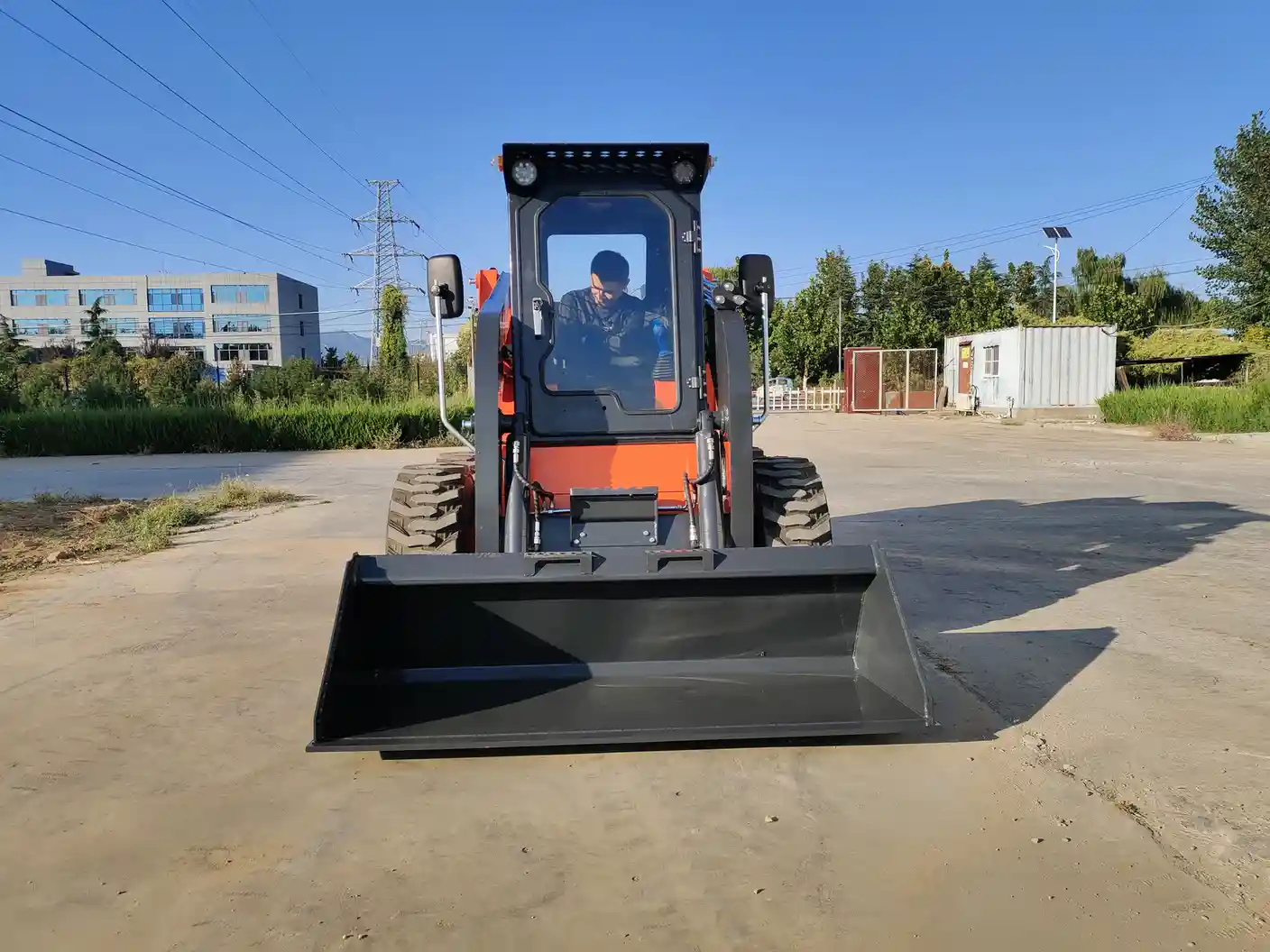
How Does a Skid Steer Work?
A skid steer works by controlling the drive on its left and right sides independently. An engine normally powers hydraulic pumps; hydraulic motors turn the wheels, and hydraulic cylinders move the lift arms and bucket. Changing the speed or direction of one side relative to the other turns the machine without angling its wheels.
The easiest way to understand the machine is to separate three jobs: moving the chassis, positioning the attachment, and powering the tool. They share an energy source, but they are not the same function. This guide explains conventional engine-powered wheeled skid steers; exact pump arrangements, controls and electric-machine designs vary by model.
From Engine Power to Useful Work
In a typical hydraulic skid steer, the engine rotates pumps that move oil through controlled circuits. The oil transfers power to motors that rotate or cylinders that extend and retract. Valves and pump controls regulate the direction and amount of movement requested by the operator.
| Power path | What converts the energy? | Visible result |
|---|---|---|
| Engine to travel hydraulics | Left and right hydraulic drive motors | Forward travel, reverse and steering |
| Engine to implement hydraulics | Lift and tilt cylinders | Arms rise or lower; bucket curls or dumps |
| Engine to auxiliary hydraulics | A motor or cylinder on a powered attachment | An auger rotates or a grapple opens and closes |
This is a functional map, not a plumbing diagram. A machine can have multiple pumps and circuits, even when they share hydraulic oil or engine power. SANY’s explanation of skid-loader components describes hydraulic motors for travel and cylinders for the working equipment. The exact machine schematic is needed for service work.
How Skid Steering Changes Direction
Unlike a car, a conventional skid steer does not point its front wheels into a turn. Its wheels remain aligned with the chassis. The front and rear wheels on each side run together, while the two sides can move independently. A speed difference makes the tires scrub sideways against the ground.
| Left side | Right side | Machine movement |
|---|---|---|
| Forward | Forward at the same speed | Straight forward |
| Forward more slowly | Forward faster | Curves left |
| Forward faster | Forward more slowly | Curves right |
| Reverse | Reverse at the same speed | Straight backward |
| Reverse | Forward | Tight counter-rotation to the left |
These are wheel-motion examples, not joystick instructions. Bobcat’s working-principle guide describes independent hydrostatic transmissions for the two sides. Counter-rotation can turn the chassis around its center, but the bucket, rear corners and any projecting tool still sweep an area. A small turning radius does not mean no clearance is needed.
The trade-off is surface disturbance. Tight turns can scuff pavement, tear turf and increase tire wear. Broad, progressive turns reduce unnecessary scrubbing where the site allows them. Tracks use a similar differential-steering idea, but the undercarriage is different; see our tracked versus wheeled loader comparison.
What the Hydrostatic Drive Does
A hydrostatic transmission sends power through pressurized hydraulic fluid rather than relying on a conventional car-style gearbox for each travel-speed change. Varying pump delivery and controlling the drive circuits changes the speed and direction of the hydraulic motors. The motor output then reaches the wheels through the machine’s final-drive arrangement.
That distinction matters: hydraulic drive does not mean there are no mechanical parts between motor and tire. Some skid steers use chains and sprockets inside a chaincase. The hydraulic system controls the drive; the mechanical components transmit that rotation to the wheels.
Engine speed and ground speed are therefore different quantities. A loader can need substantial engine output for a powered attachment while moving slowly. Control features and available power determine how well a particular model combines travel and tool work.
How the Lift Arms and Bucket Move
Lift cylinders act on the loader linkage to raise or lower the attachment. Tilt cylinders change the attachment angle, allowing a bucket to curl back or dump without relying only on arm height. The cylinders produce straight-line force; the pivots and links turn that force into the required movement.
Lift geometry controls the path. A radial linkage moves through an arc; a vertical-lift linkage produces a more upright path. Neither description tells you the exact clearance or reach of every model. Compare the manufacturer’s dimensions at the height where the job happens.
Why hydraulic force is not the same as safe load capacity
Pressure acting over a cylinder’s piston area produces force, but the useful force at the attachment also depends on linkage leverage. Machine balance, attachment weight and how far forward the load sits matter too. The ability to move a load momentarily is not permission to carry it. Use the rated operating capacity and attachment-specific limits for the actual configuration.
Flow and pressure describe different things. For a given actuator, flow mainly influences movement speed, while pressure is related to the force or torque required by the load. More auxiliary flow does not automatically increase the loader’s rated lifting capacity.
How Attachments Receive Power
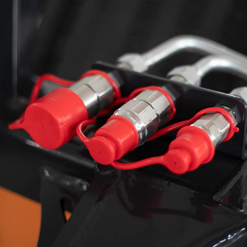
A plain bucket or pallet fork uses the loader’s lift and tilt motion and normally needs no auxiliary hydraulic connection. An auger, broom or grapple needs an additional power supply for its own movement. Auxiliary hoses connect the loader’s hydraulic circuit to the tool’s motor or cylinder.
Caterpillar’s continuous-flow explanation shows why rotating attachments need a sustained oil supply. Continuous flow maintains a selected command; high flow describes a hydraulic output capability. They are not interchangeable terms.
The mounting plate is only the mechanical connection. Before pairing a tool with a loader, compare flow range, pressure limits, couplers, any case-drain requirement, electrical controls and attachment weight. A powered quick coupler can lock an attachment mechanically without automatically connecting its hydraulic hoses.
Do Both Joysticks Control the Wheels?
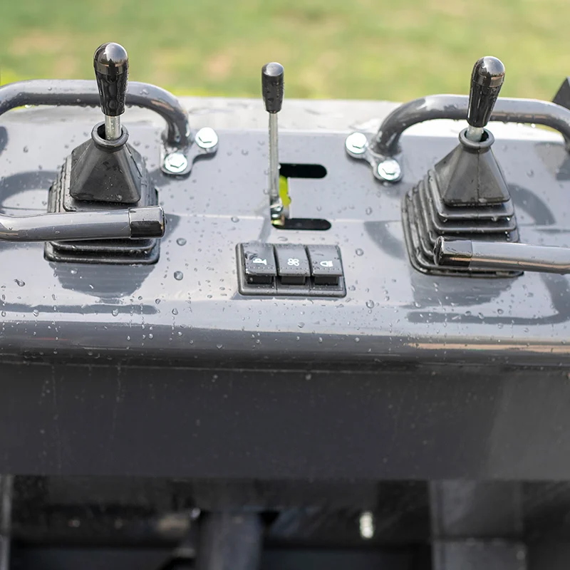
Not on every skid steer. Control layout depends on the model and selected pattern. In a common ISO layout, the left joystick handles travel and steering while the right handles lift and tilt. H-pattern controls distribute travel and working functions across both hands. Traditional systems can use hand levers for travel and pedals for lift and tilt.
Bobcat’s selectable-control guide explains the ISO/H distinction. Do not assume that a familiar-looking joystick has the same assignment as another machine. Check the control decal, selected mode and operator manual before operating.
How the Systems Work Together
During material handling, the travel system positions the loader, the lift circuit changes arm height, and the tilt circuit controls the bucket angle. With a powered tool, auxiliary hydraulics add another demand. These functions can overlap, but the engine and hydraulic system have finite output.
For example, a hydraulic broom needs suitable oil flow while the loader advances at an appropriate ground speed. Buying only by engine horsepower misses that relationship. Tool requirements, travel controllability and cooling capacity help determine whether the complete package suits sustained work.
Safety Systems Are Part of How It Works
Seat, restraint-bar or other interlocks can inhibit travel and hydraulic functions when required operating conditions are not met. Their behavior varies by machine. Never bypass them to make a loader move or an attachment operate.
An interlock is not a mechanical support for raised arms. Follow the manufacturer’s shutdown and support procedure before any permitted service work beneath raised equipment. NIOSH skid steer safety guidance emphasizes lift-arm supports and safe entry and exit. This explanation of principles does not replace operator training or the machine and attachment manuals.
What to Check When Comparing Machines
Ask for the control pattern, travel-drive arrangement, rated capacity, lift-height and reach dimensions, and the auxiliary hydraulic specification. For powered tools, obtain a matched machine-and-attachment configuration rather than two separate lists of headline specifications.
For a broader introduction, read what a skid steer loader is. To discuss a working package, explore Zentramo’s skid steer loaders and send your main task, required load, access dimensions and planned attachments.