
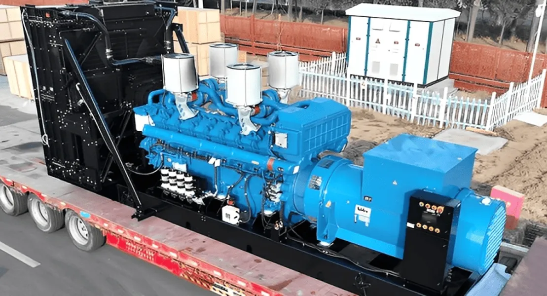
How to Adjust Generator Governor and RPM Settings
A generator governor controls engine fuel or throttle input so the alternator can hold the required frequency as electrical load changes. The safe way to adjust it is not to chase a generic RPM number. First identify the generator’s rated frequency, alternator pole count, governor type, and manufacturer procedure. Then measure the baseline, make one small change at a time, and confirm performance at no load and under controlled load.
Important: Governor work may expose you to rotating parts, hot surfaces, fuel, battery energy, and lethal voltage. Stop if the correct service manual, test instruments, load bank, or qualified personnel are not available. Do not change governor settings on a grid-connected or paralleled generator unless the work is directed by the system engineer or generator manufacturer.
Quick Answer: The Correct Adjustment Sequence
- Confirm the nameplate frequency, voltage, phase, rated speed, alternator pole count, and governor model.
- Remove the load, isolate the generator from the building or bus, and inspect the linkage, springs, actuator, fuel system, and wiring before changing a setting.
- Warm the engine according to its manual and record no-load frequency, voltage, and RPM.
- Adjust only the documented speed setting. Use small increments and allow the speed to stabilize after each change.
- Apply load in controlled steps and record frequency, voltage, RPM, recovery time, smoke, temperature, and hunting.
- Adjust gain, stability, or droop only when the controller manual calls for it and the technician understands the effect of each parameter.
- Restore covers and guards, save the final settings, and keep a before-and-after test record.
Understand the Relationship Between RPM and Frequency
For a conventional synchronous alternator, speed, frequency, and pole count are related by:
Synchronous speed (RPM) = 120 × frequency (Hz) ÷ number of poles
| Alternator | 50 Hz synchronous speed | 60 Hz synchronous speed |
|---|---|---|
| 2-pole | 3,000 RPM | 3,600 RPM |
| 4-pole | 1,500 RPM | 1,800 RPM |
| 6-pole | 1,000 RPM | 1,200 RPM |
These are synchronous speeds, not universal adjustment targets. Inverter generators, induction machines, belt-driven systems, and specialized alternators may behave differently. Even on a conventional set, the manufacturer’s no-load target may intentionally differ from rated frequency so the unit settles correctly when loaded. Use the nameplate and the exact service manual as the controlling references.
Governor adjustment and voltage-regulator adjustment are different jobs. The governor primarily controls engine speed and therefore output frequency. The AVR controls excitation and therefore voltage. A low-voltage complaint does not automatically justify changing the governor.
Identify the Governor Before You Touch a Setting
Mechanical governor
A mechanical governor normally uses flyweights, a spring, and a linkage connected to the throttle or fuel rack. Depending on the engine, the accessible control may set spring tension, high-speed position, sensitivity, or droop. Do not move a spring to another hole or reposition the governor arm unless the engine manual gives that procedure. Those changes can alter the full control range, not just fine-tune speed.
Electronic governor
An electronic system uses a speed sensor, controller, and actuator. Its menu or potentiometers may include rated speed, gain, stability, ramp, deadband, and droop. Record every original value before making a change. A wrong gain or stability setting can cause hunting even when the speed setpoint is correct.
Engine ECU or integrated genset controller
Modern industrial generator sets may control speed through the engine ECU and a genset controller. Some parameters are password-protected or depend on engine calibration. Use the approved service software and configuration file; do not copy values from a different engine or controller.
Tools, Records, and Safety Preparations
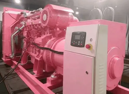
Prepare the equipment specified by the manufacturer. A typical controlled adjustment may require:
- The generator, engine, and governor manuals for the exact model and serial number
- A calibrated frequency meter or true-RMS multimeter with a Hz function
- A suitable tachometer when the manual requires direct speed measurement
- A correctly rated load bank or a controlled facility load
- Insulated tools, required PPE, and lockout/tagout equipment
- A worksheet for original settings, each adjustment, and test readings
Never use engine sound as the only speed indicator. A tachometer without a frequency measurement can also miss alternator configuration or coupling problems. Measure both RPM and electrical frequency when practical.
Before starting, open the generator output breaker and prevent unintended transfer or parallel connection. Check oil, coolant, fuel, battery condition, air restriction, leaks, loose wiring, binding linkage, weak springs, damaged mounts, and fault history. Correct these problems first. Governor tuning cannot compensate for an engine that is misfiring, starving for fuel, overheating, or mechanically binding.
Step-by-Step Governor and RPM Adjustment
1. Record the baseline
With the output breaker open, start the set according to the operating manual and let it reach normal operating temperature. Record no-load Hz, voltage, and RPM, plus any controller alarms or oscillation. Compare them with the manufacturer limits. If the engine races, hunts severely, has abnormal noise, leaks, or produces unsafe voltage or frequency, shut it down instead of continuing.
2. Confirm that adjustment is actually needed
If frequency is stable but voltage is wrong, investigate the excitation and AVR system. If both speed and frequency fluctuate, inspect the fuel supply, air system, ignition on spark-ignited engines, linkage, speed sensor, and actuator before tuning. If speed is correct but frequency is not, verify the pole count, instrument accuracy, coupling, and alternator configuration.
3. Adjust the rated-speed control in small increments
Locate the exact speed-setting point shown in the model-specific manual. On a mechanical governor this may be a spring-tension nut or documented speed screw. On an electronic governor it may be a controller parameter. Mark or record the original position. Make one small change, keep clear of rotating and live parts, and wait for the reading to stabilize before deciding on the next change.
Do not use the idle stop, maximum-fuel stop, overspeed trip, or AVR voltage control as substitutes for the rated-speed setting. Do not defeat an overspeed protection device to reach the target.
4. Check stability at no load
After the frequency reaches the approved no-load range, watch it long enough to identify slow drift or repeated oscillation. If the engine hunts, return to the last stable setting and diagnose the cause. On electronic governors, gain and stability interact; changing both at once makes the result difficult to interpret. On mechanical systems, excessive sensitivity or a binding linkage can create similar symptoms.
5. Test under controlled load
Close the breaker only when the test arrangement is safe. Apply load in the increments required by the commissioning procedure and remain within the set’s rated duty. At each step, record kW or kVA, frequency, voltage, RPM, exhaust condition, temperature, and stabilization time. The goal is not merely a correct no-load reading. The generator must accept and reject load without unacceptable frequency deviation, hunting, stalling, overspeed, or protective trips.
6. Set droop only for the intended operating mode
Droop is the intentional reduction in governed speed or frequency as load increases. It can support stable load sharing between generator sets, while isochronous control aims to maintain a constant frequency on an isolated bus. The correct choice depends on the switchgear, load-sharing controller, and system design. Do not set droop by guesswork on a paralleled system; an incorrect value can cause poor kW sharing or circulating power between sets.
7. Verify load rejection and protection
Reduce the load in controlled steps and confirm that the engine does not overspeed. Verify the functions required by the commissioning plan, including alarms, shutdowns, breaker operation, and return to stable no-load frequency. Do not intentionally test an overspeed trip by raising the speed unless the manufacturer provides a safe simulated test procedure.
8. Secure and document the final setting
Stop and isolate the generator before tightening locknuts, replacing covers, or working near the linkage. Restore all guards. Save electronic settings according to the controller manual and record the final values, ambient conditions, instruments used, and readings at each load point.
How to Judge Whether the Adjustment Passed
| Check | Accept when | Stop and investigate when |
|---|---|---|
| No-load frequency | It is stable and within the exact manufacturer limit | It drifts, hunts, or requires an extreme setting |
| RPM-to-Hz relationship | It matches the alternator configuration and instrument readings | RPM and frequency are inconsistent |
| Load acceptance | Frequency recovers within the specified time without instability | The engine stalls, smokes heavily, or trips repeatedly |
| Load rejection | Speed rise stays inside the specified transient limit | Overspeed occurs or protection fails |
| Voltage | It remains within the alternator and AVR limits | Voltage remains abnormal after speed is correct |
| Parallel operation | kW sharing and frequency control follow the system design | Units fight for load or reverse-power alarms occur |
Use the pass/fail limits in the applicable data sheet, controller manual, project specification, and commissioning standard. A generic internet tolerance is not a substitute for the approved acceptance criteria.
Common Mistakes and What They Usually Mean
- Adjusting by ear: The engine may sound normal while the frequency is outside the equipment’s acceptable range.
- Changing the AVR to correct Hz: This can create a second fault without correcting engine speed.
- Tuning around a fuel or air problem: Clogged filters, air in diesel fuel, dirty carburetors, and restricted airflow can all look like poor governor response.
- Changing several settings together: You lose the ability to identify which change improved or destabilized the set.
- Setting only at no load: A correct idle reading does not prove acceptable load pickup, steady-state regulation, or load rejection.
- Copying another unit’s values: Engine ratings, actuator travel, sensor tooth count, firmware, and alternator poles can differ.
- Confusing droop with instability: Designed load-dependent frequency change is different from repeated hunting.
When to Call a Generator Technician
Arrange professional service when the generator is connected to an automatic transfer system, operates in parallel, uses protected ECU settings, has exposed live adjustment points, or repeatedly trips on overfrequency or underfrequency. Professional diagnosis is also appropriate when the linkage does not move freely, an actuator cannot reach its commanded position, the magnetic pickup signal is unstable, or correct frequency cannot be maintained from no load to rated load.
For a new industrial generator set, define the required voltage, frequency, phase, operating duty, transient load, and parallel-operation requirements before commissioning. Zentramo can configure generator-set controls and provide project-specific documentation for the selected engine, alternator, and controller. Review our generator set solutions or contact our technical sales team with your load schedule and site conditions.
Frequently Asked Questions
Can I set a generator governor without a tachometer or frequency meter?
No reliable adjustment should be made by sound alone. At minimum, use the instrument required by the manufacturer’s procedure. A frequency meter is often the most direct way to check output on a conventional synchronous generator, while a tachometer helps confirm the mechanical speed. For commissioning, use calibrated instruments and record both when possible.
Should every 60 Hz generator run at 3,600 RPM?
No. A 2-pole synchronous alternator operates at 3,600 RPM for 60 Hz, while a 4-pole unit operates at 1,800 RPM and a 6-pole unit at 1,200 RPM. Always verify the alternator pole count and nameplate. Inverter and other specialized designs may not follow a fixed engine-speed relationship.
Why does generator frequency drop when load is applied?
A brief drop can occur while the engine and governor respond to the increased torque demand. A continuing drop may indicate normal configured droop, excessive load, restricted fuel or air supply, linkage or actuator problems, or incorrect governor tuning. Compare the observed response with the exact model’s specification.
What causes a generator to hunt after governor adjustment?
Possible causes include excessive governor gain or sensitivity, binding linkage, a weak or misplaced spring, unstable speed-sensor input, fuel-system problems, ignition faults, or actuator issues. Return to the recorded baseline and diagnose the engine and control system before making further changes.
Can governor adjustment fix low generator voltage?
Only when low voltage is a consequence of incorrect engine speed on a design where voltage changes with speed. If frequency is correct but voltage is not, inspect the AVR, excitation circuit, sensing wiring, windings, and load conditions according to the alternator manual.
Official Technical References
- Woodward PSG Governor Manual 37013 — governor speed droop and parallel-operation principles.
- Woodward 505DE Digital Governor Manual — rated speed, droop, and electronic governor parameters.
- Kohler TP-6967 Installation Manual — frequency measurement, warm-up, speed adjustment, stability, and verification sequence.
- STAMFORD BC Alternator Owner’s Manual — overspeed and qualified-personnel warnings during generator adjustment.