
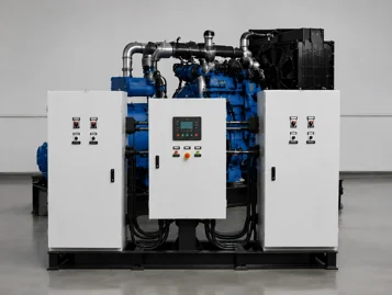
How to Install a Generator Transfer Switch
A generator transfer switch is the device that keeps utility power and generator power from feeding the same load at the same time. Installing it correctly is therefore not just a wiring task; it is a coordinated power-system project involving load calculations, equipment selection, isolation, protection, control wiring, testing, and approval.
Safety note: Transfer-switch installation exposes workers to service-level voltage and potential backfeed. It must be designed and completed by a qualified electrician in accordance with the switch manufacturer’s instructions, the generator manual, the approved one-line diagram, and all applicable local codes. Do not use this article as a substitute for the model-specific installation manual.
This guide explains the professional workflow for installing either a manual transfer switch or an automatic transfer switch (ATS), with extra attention to the decisions that prevent unsafe backfeed, nuisance transfers, and commissioning failures.
What a Generator Transfer Switch Does
A transfer switch connects a selected load to one of two power sources: the normal utility supply or the standby generator. Its interlocking mechanism prevents the two sources from being connected together in an ordinary open-transition system. That isolation is essential because uncontrolled backfeed can endanger utility workers, damage equipment, and create fire or shock hazards.
A manual transfer switch requires an operator to start the generator and move the load. An ATS monitors the normal source, signals the generator to start when the source fails, waits until generator voltage and frequency are acceptable, transfers the load, and later returns it to utility power after the normal source is stable.
Before Installation: Define the System
The fastest way to create installation problems is to buy the switch before defining the electrical system. Record the following project data first:
- System voltage, frequency, and phase: for example, 400/230 V, 50 Hz, three-phase, four-wire.
- Required current and load type: include continuous load, motor-starting current, nonlinear loads, and planned expansion.
- Transfer scope: whole facility, an emergency distribution board, or selected essential circuits.
- Generator operating mode: manual start, remote start, or fully automatic standby operation.
- Earthing and neutral arrangement: determine whether the neutral is solid or switched and whether the generator is treated as a separately derived source under the governing rules.
- Transition method: open transition is common; delayed, closed, or bypass-isolation arrangements require different engineering and controls.
- Installation environment: indoor or outdoor location, ambient temperature, dust, moisture, corrosive conditions, and required enclosure rating.
- Fault-duty requirements: verify the switch’s short-circuit withstand/closing rating and its coordination with upstream protective devices.
Also confirm whether the transfer equipment is service-entrance rated. A service-entrance application has additional disconnecting, bonding, protection, and utility requirements. Never assume that an ordinary downstream ATS can replace service-entrance equipment.
Manual or Automatic?
| Decision factor | Manual transfer switch | Automatic transfer switch |
|---|---|---|
| Typical application | Portable generator or supervised backup | Standby power for unattended or critical loads |
| Generator starting | Usually started by an operator | Remote-start contacts signal the genset controller |
| Transfer action | Operator moves the switch after checking conditions | Controller transfers after source qualification |
| Control requirements | Minimal | Source sensing, timers, start circuit, alarms, and settings |
| Best fit | Noncritical loads where an operator is available | Facilities that need automatic continuity of power |
Tools and Project Documents
The installer should work from an approved package rather than memory. At minimum, it should contain the one-line diagram, transfer-switch and generator manuals, conductor and conduit schedule, protection study or device schedule, panel schedules, control schematic, cable identification plan, inspection requirements, and commissioning procedure.
Typical professional test equipment includes an appropriately rated multimeter, phase-rotation meter, insulation-resistance tester when permitted by the connected equipment, torque tools, lockout/tagout equipment, calibrated current or load measurement tools, and the required personal protective equipment. Instrument category and voltage ratings must match the system.
Professional Installation Process
1. Confirm Ratings, Compatibility, and Approvals
Compare the ATS nameplate with the approved design. Verify poles, voltage, frequency, phase, rated current, enclosure type, fault rating, transition type, service-entrance status, and control supply. Then confirm that the generator controller provides the required remote-start interface and that the selected ATS logic is compatible with it.
Obtain any required permits and utility approval before interrupting service. For a commercial or industrial project, review selective coordination, emergency-system classification, fire-code requirements, and the operating sequence with the engineer and authority having jurisdiction.
2. Establish a Safe Shutdown and Isolation Plan
Identify every possible source of energy, including utility, generator, photovoltaic, battery storage, UPS output, control power, and backfeed from interconnected equipment. Follow the site’s approved lockout/tagout procedure: shut down in an orderly manner, operate the correct isolating devices, apply locks and tags, release stored energy, and verify isolation with properly rated test equipment.
Do not rely on an indicator lamp, controller display, or an open breaker alone. The qualified worker must verify absence of voltage using the approved test method before touching conductors.
3. Mount the Transfer Switch
Install the enclosure on a rigid, level support in the approved location. Maintain the manufacturer’s working clearances, ventilation needs, cable-bending space, and access to handles, covers, labels, and test controls. Outdoor installations require a suitable enclosure and carefully sealed cable entries that do not defeat drainage or environmental protection.
Plan conduit entry positions before drilling or punching. Metal chips, swarf, and dust must not remain inside the enclosure, because conductive debris can cause tracking or short circuits.
4. Route Utility, Generator, and Load Conductors
Route each source and load conductor according to the approved drawings. Keep power conductors separated from low-voltage control and communication wiring where required. Preserve phase identification from source to load, respect conductor bending radii, protect cables from sharp edges, and bond metallic enclosures and raceways as designed.
The correct conductor size depends on current, insulation rating, installation method, ambient temperature, grouping, voltage drop, fault duty, protective devices, and local code. Use the project’s engineered cable schedule instead of a generic online sizing table.
5. Terminate Power and Grounding Connections
Identify the terminals for normal source, emergency source, load, neutral, and protective earth from the exact model drawing. Prepare conductors with approved lugs and terminate them to the manufacturer’s specified torque. Record torque values when the quality plan requires it.
Neutral and grounding arrangements deserve special review. An incorrect neutral bond or an incorrectly selected three-pole/four-pole switch can create circulating current, nuisance protection operation, or an unsafe touch-voltage condition. The engineer or qualified electrician must determine the arrangement for the specific system.
6. Connect ATS Control and Generator Start Circuits
For an ATS, connect normal-source sensing, emergency-source sensing, remote-start contacts, auxiliary contacts, alarms, load-shed outputs, and communication wiring exactly as shown in the switch and generator schematics. Confirm whether contacts are dry, normally open, or normally closed and verify the permitted control voltage and current.
Do not confuse the generator controller with the transfer switch. The controller starts, stops, protects, and monitors the generator set; the ATS selects the source feeding the load. Their settings and interconnection must be coordinated, but they perform different jobs.
7. Inspect Before Energization
Before replacing barriers and energizing the system, complete a documented inspection:
- Compare every power and control connection with the approved drawings.
- Confirm source, load, phase, neutral, earth, and control-wire labels.
- Check lug preparation and recorded torque values.
- Remove tools, wire offcuts, packing material, and conductive debris.
- Verify barriers, dead fronts, covers, interlocks, and manual handles are correctly installed.
- Check protective-device ratings and settings against the approved schedule.
- Confirm that the generator is ready for commissioning and that its emergency stop is accessible.
8. Commission the Transfer Sequence
Commissioning must follow the model-specific manual and the project’s approved test plan. Do not improvise a utility-failure test. A typical sequence verifies:
- Normal-source voltage, frequency, phase rotation, and ATS indication.
- Generator manual operation and stable output before automatic testing.
- Remote-start operation from the ATS.
- Engine warm-up and emergency-source qualification delays.
- Transfer to generator without paralleling sources in an open-transition system.
- Voltage, frequency, phase rotation, and load current on generator power.
- Load-step response and any load-shedding sequence.
- Utility return sensing and retransfer delay.
- Generator cool-down and stop sequence.
- Alarms, event logs, remote annunciation, and emergency controls.
Some manufacturers require a manual mechanical-operation check while all sources are isolated before electrical operation. Follow the exact order in the product manual; operating a transfer mechanism under the wrong conditions can cause injury or equipment damage.
Generator Transfer Switch Commissioning Checklist
| Check | Acceptance evidence |
|---|---|
| Nameplate and design match | Voltage, poles, current, transition type, enclosure, and fault rating recorded |
| Mechanical installation | Secure mounting, clear access, correct cable entries, barriers installed |
| Power terminations | Phase identification checked and required torque records completed |
| Neutral and earthing | Arrangement verified against one-line diagram and local requirements |
| Control circuits | Start, sensing, alarm, auxiliary, and load-shed functions tested |
| Automatic sequence | Start, qualification, transfer, retransfer, cool-down, and stop times recorded |
| Loaded operation | Voltage, frequency, phase rotation, current balance, and generator response acceptable |
| Handover | Labels, as-built drawings, settings, test report, manuals, and training delivered |
Common Installation Mistakes
Using the Wrong Switch Rating
Rated current alone is not enough. Voltage, phase, pole count, transition type, service-entrance status, enclosure, and fault rating all matter. A switch that carries the normal load may still be unsuitable for the available fault current or grounding scheme.
Assuming Any Neutral Arrangement Will Work
The decision to switch or solidly connect the neutral is system-specific. Treat it as a design decision, not a field preference.
Mixing Power and Control Requirements
Applying the wrong voltage to a remote-start or sensing terminal can damage both the ATS controller and the generator controller. Verify contact type, control voltage, polarity where applicable, and cable separation.
Skipping Phase-Rotation Checks
A phase-sequence mismatch can reverse motors after transfer even when line-to-line voltage appears correct. Verify rotation at both sources before applying the load.
Testing Without an Approved Sequence
Opening utility power without coordination can interrupt critical processes. Manually moving a mechanism under load may also be prohibited. Use a written, manufacturer-approved commissioning plan and notify affected personnel.
Backfeeding Through an Improvised Connection
Never connect a generator to building wiring through a male-to-male cord, an unapproved inlet, or another method that can energize the utility side. OSHA guidance states that a generator should not be attached directly to a structure’s electrical system unless a qualified electrician has installed it with a transfer switch.
After Installation: Documentation and Maintenance
Handover should include the approved as-built one-line diagram, control schematic, cable schedule, protection settings, ATS timer and threshold settings, commissioning results, manuals, warranty information, and operator training record. Label both sources and the load clearly.
Create a maintenance plan based on the manufacturer’s instructions and site risk. Typical checks cover enclosure condition, water or dust ingress, loose or overheated connections, controller alarms, mechanical operation, source sensing, generator start, transfer/retransfer performance, and battery condition. Critical installations may also require periodic load-bank or integrated system testing.
Frequently Asked Questions
Can I install a generator transfer switch myself?
Transfer-switch installation involves service-level voltage, backfeed risk, grounding and bonding decisions, protective-device coordination, and regulatory approval. It should be performed by a qualified electrician who follows the exact equipment manuals and local requirements.
What size transfer switch do I need?
The switch must be selected for the engineered load and system, not simply the generator’s kW rating. Check voltage, phase, continuous current, starting loads, number of poles, neutral arrangement, fault rating, transition type, enclosure, and whether it is serving the whole facility or only essential circuits.
Does every standby generator need an ATS?
No. A supervised backup system may use an approved manual transfer switch. An ATS is appropriate when automatic starting and unattended transfer are required. In either case, the transfer equipment must positively prevent unsafe connection of utility and generator sources.
How long should an ATS wait before transferring?
There is no universal setting. Source-failure delay, generator warm-up, transfer, retransfer, and cool-down values depend on the generator, the load, the facility’s operating needs, and the manufacturer’s limits. Commission the settings under an approved sequence.
Why does the generator start but the ATS does not transfer?
Possible causes include unacceptable generator voltage or frequency, an incorrect sensing connection, a control fuse or supply problem, a mechanical interlock, incorrect mode selection, a timer still running, or a wiring/settings mismatch. A qualified technician should use the event log, schematic, and manufacturer test procedure to diagnose it.
Plan the Generator and ATS as One System
A reliable installation starts with a coordinated generator, controller, transfer switch, protection scheme, and load plan. Zentramo supplies diesel and gas generator set solutions with options for automatic transfer and AMF-compatible control. For a project-specific configuration, send the system voltage, frequency, phase, required load, motor-starting details, installation environment, and desired transfer sequence through the Zentramo contact page.